KF7Max Spectra 9000 proect
Convert a Spectra 9000 into a
110w mobile VHF FM RF amplifier for an HT.
I am updating the below content to account for the fact the project was finished and works great. I am revamping the project to use Arduino control and will update the info as I go along. ..KF7MAX 1/5/24
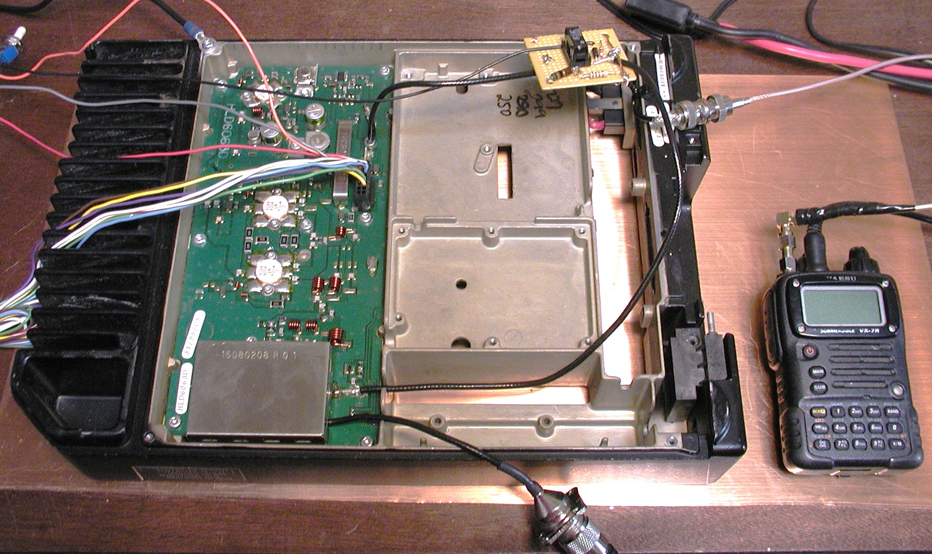
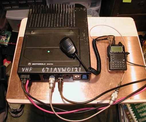
A few years ago, HiDARG accepted a donation of some radios from a public agency in Washington State. We currently have about 10 UHF units and 10 VHF units. Each unit is able to pump out 110 watts of power. These were headed for the re-cycle bin unless some kind of use could be found for them. I started to do some research on the radios and found out that the VHF units are able to support the upper VHF ham band. Some issues we had were getting the software and cables to program them. Plus once programmed the control heads would only allow about 9 channels or so to be accessed. Very limited to say the least. Then an idea occurred to me. What if I could modify one and turn it into a basic power amp for an HT, or other mobile rig. I began to do some research and track down just how I could accomplish this. I hope to have more details about what I found out. Suffice to say, with the information obtained, I proceeded to come up with a basic design for an interface to drive the 110watt power amp with my HT. In the weeks to come I will document some of my progress. The goal is to determine if this is a viable method of putting these surplus radios back to good use. The initial prototype interface is done, and testing will commence once the circuit boards are obtained and populated with the components. Ideally it will be nice to be able to have two or more power settings if possible say 50w and 110w. From the Motorola specs I believe the board was designed to do this. That remains to be seen. My initial testing showed a very clean signal. However once I have the prototype board setup and working, I will need to put it on a spectrum analyzer to see just how clean things really are. Given Motorola's tight specifications, I don't' see any issues here unless my HT is out of whack.
As a full radio, (non-hacked) the particular units we have are able to transmit and receive between 146-174 mhz. Based on this, it can be assumed that the PA board in the unit is at least able to do the same. The interface pins (described in the finals schematic) are the primary control system to the PA board. They handle keying the PA as well as providing feedback on temp and current sensing. The interface board provides pins to access these circuits for those wanting to expand on the project.
DISCLAIMER:
You are assumed to know what your doing if you attempt this project. I do not recommend it for beginners. Heck I am a self taught electronics geek long before I became a ham, and have had my share of making things smoke. Some times on purpose, but that is a story for another day. I can offer some advice and will answer any questions to the best of my scattered knowledge, but if you burn your house down, fry the neighbors dog, or cause general mayhem, your on your own. I take no responsibility for what you do with this information. It should be said that proper RF precautions apply here as well.
Basic Operation:
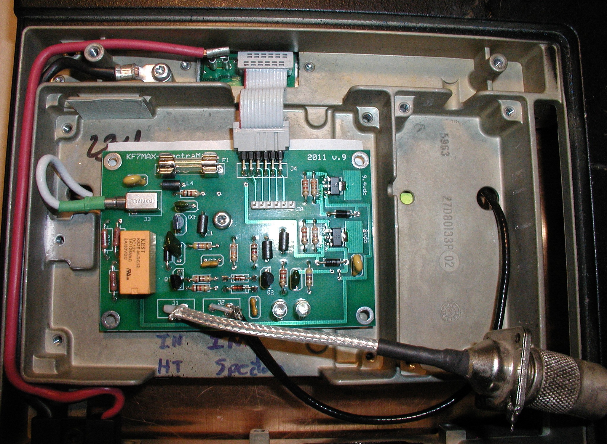
With no interface board connected to the PA side, no voltage is drawn through the main power connection. With the interface board connected, about .45 amps are drawn depending upon if you have the 2vdc LM319 regulator set to switched or unswitched mode or have opted to have the LED's connected. The latest rev(1.1) of the interface board has a location for an optional switch for those that want to have the PA be switchable on/off via the interface board, rather than through a main heavy duty power switch coming off the main power leads. I have elected to do that feature on my unit.
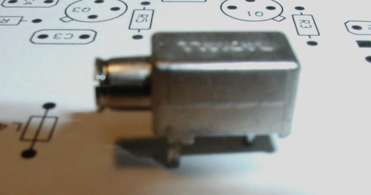
Ok moving on, when the board detects RF on the Input, it toggles on the K1 relay, the output from my 1watt HT is feed through the 2db pad. The DPDT relay also in turn supplies the 9.4vdc to the PA finals as well as the "bias" +2vdc to the finals as well. This actually controls the ability of the PA to do either 110w or 50w. If the voltage is set to about +1vdc then the PA board is in 50w mode. I have not confirmed if variouse voltages will give a power level in between these two values. What I do know is that if you have less than +1vdc, nothing happens. When I have time maybe a modification to the actually PA board would be in order. As a note this is a class A/B amp and will not support SSB. One other thing to mention is that the SO-239 connection to the antenna is also the input to the HT when the relay is not activated. In normal operation, the +9.44vdc will activate the pin diodes on the PA board, and remove the output RF from the input pre-amp on the board. With this hack we do not have to worry about it as the relay takes care of this for us.
DB Pad:
The most important part of setting this up for use, is to decide what type of input your going to drive it with. I opted to use my HT which is my all around general mobile rig. I have my pad set for about 2db attenuation. And drive the PA with 1watt. This gives me about 100mw of input power to the PA board. In my experimentation, levels below this do not properly drive the PA board. If you wish to drive it with 5 watts or greater you will have to provide the appropriate pad. And of course the pad will need to be able to handle the RF power. I have 1 watt resistors on my pad, and they do get a little warm during operation. Any resistor larger than 1 watt will not connect directly to the board, so you will need to rig up your own pad set off to the side of the board. Keep in mind it will may need some shieldingof course. Also keep in mind that the contacts in the relay have a low rating 1a at 125vac/2a30vdc since I have placed the pad prior to the relay, this should not be a problem for the relay.
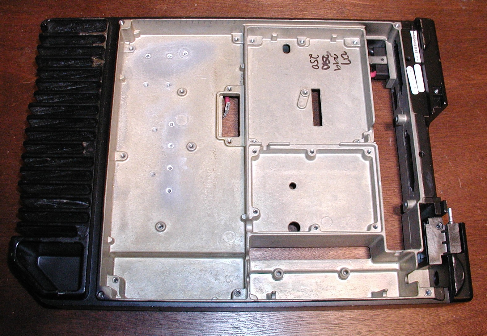
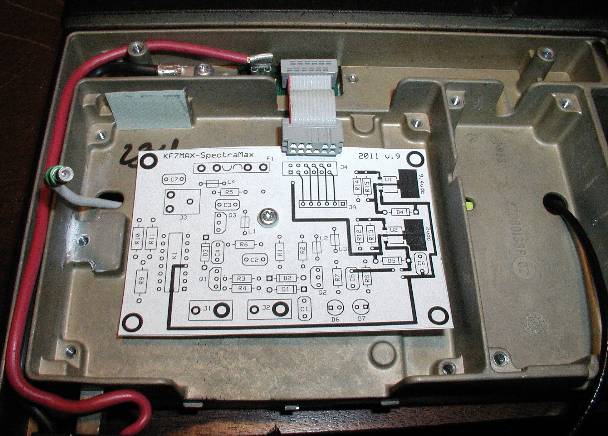
This is about 7lbs or so of an aluminum casting left after I gutted it. I really like how modular everything is. Very easy to reverse back to original setup if need be. I decided to remove the power amp deck in order to reseat the power transistors with fresh heat sink goop. In this picture you can see in the center opening the end of a wire with its connecting lug peeking through from underneath. This supplies the amplifier deck with the 13.5vdc.
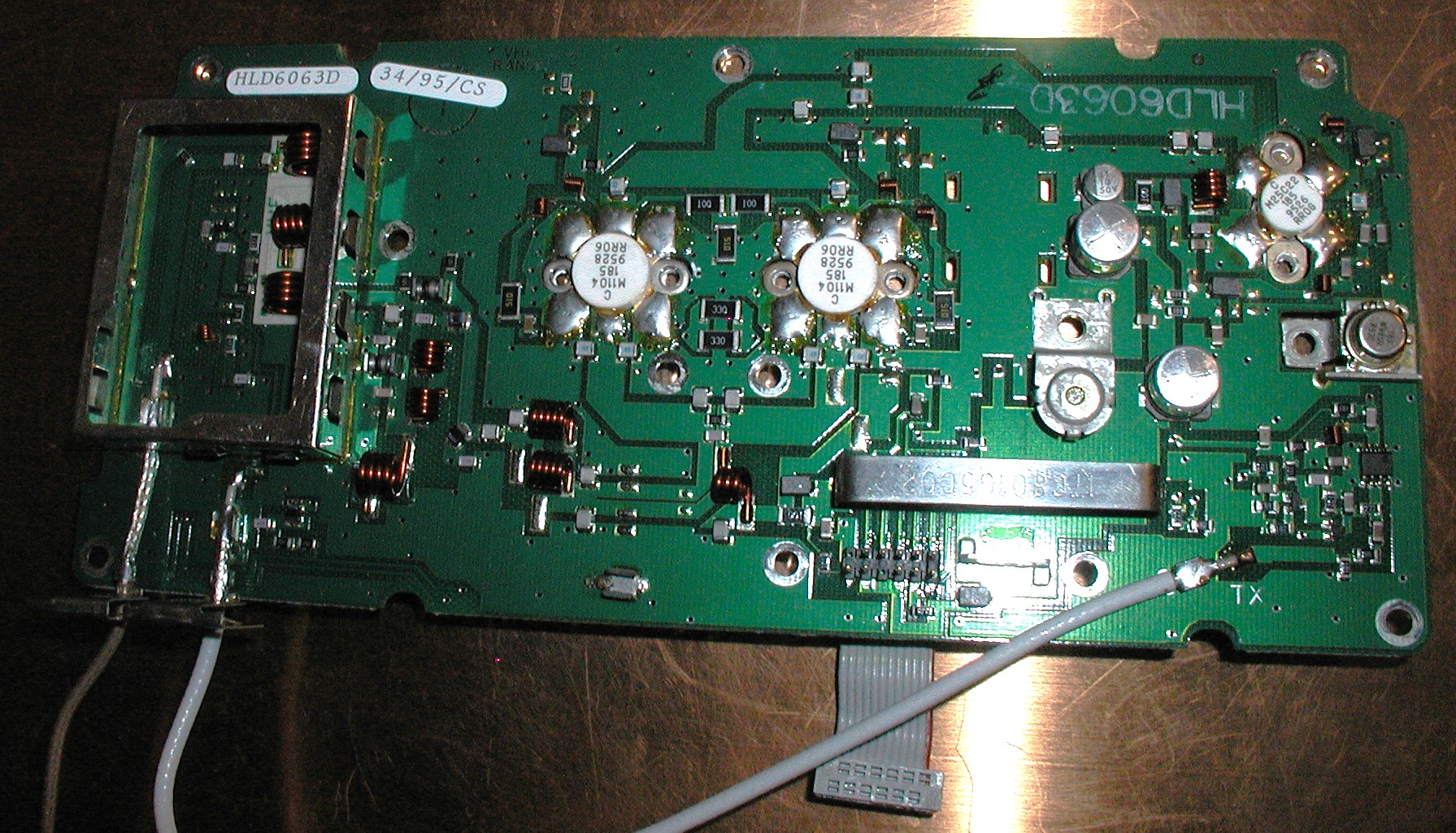
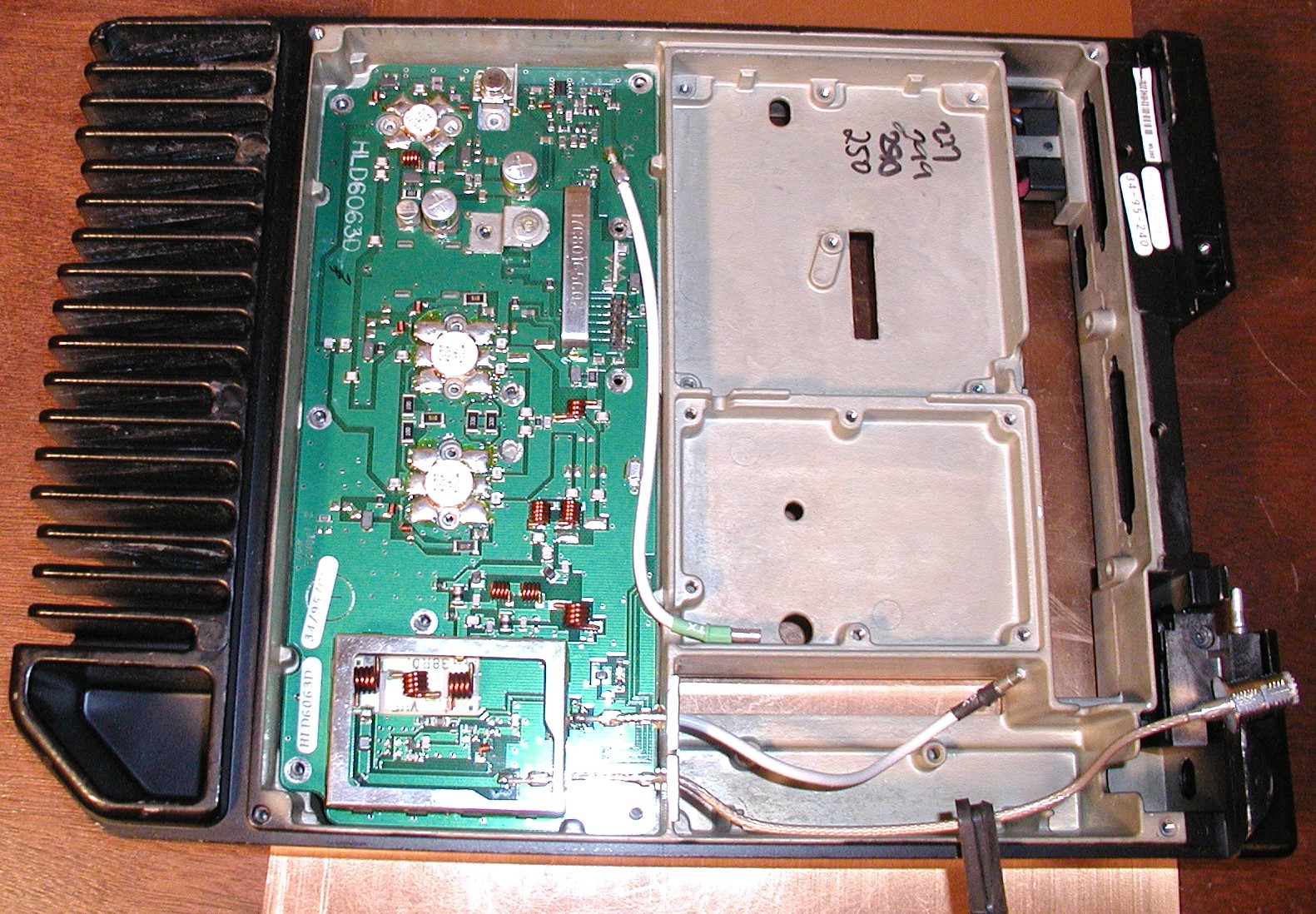
The power amp deck now reseated and back in position after it's cleaning and re-applying more heat sink goop. Notice the white coax coming from the top of the board. This is the TX input to the drive pre-amp. You can see the small connector on its end. This plugs into a connector on the main control board.
